Jones calculus
In optics, polarized light can be described using the Jones calculus, invented by R. C. Jones in 1941. Polarized light is represented by a Jones vector, and linear optical elements are represented by Jones matrices. When light crosses an optical element the resulting polarization of the emerging light is found by taking the product of the Jones matrix of the optical element and the Jones vector of the incident light. Note that Jones calculus is only applicable to light that is already fully polarized. Light which is randomly polarized, partially polarized, or incoherent must be treated using Mueller calculus.
Contents |
Jones vectors
The Jones vector describes the polarization of light.
The x and y components of the complex amplitude of the electric field of light travel along z-direction,  and
and  , are represented as
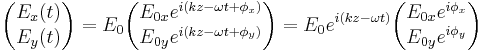 .
.
Here  is the Jones vector (
 is the imaginary unit with
  ). Thus, the Jones vector represents (relative) amplitude and (relative) phase of electric field in x and y directions.
The sum of the squares of the absolute values of the two components of Jones vectors is proportional to the intensity of light. It is common to normalize it to 1 at the starting point of calculation for simplification. It is also common to constrain the first component of the Jones vectors to be a real number. This discards the phase information needed for calculation of interference with other beams. Note that all Jones vectors and matrices on this page assumes that the phase of the light wave is 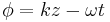 , which is used by Hecht. In this definition, increase in
  (or
(or  ) indicates retardation (delay) in phase, while decrease indicates advance in phase. For example, a Jones vectors component of (
 ) indicates retardation by
  (or 90 degree) compared to 1 (
 ). Collett uses the opposite definition (
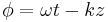 ). The reader should be wary when consulting references on Jones calculus.
The following table gives the 6 common examples of normalized Jones vectors.
| Polarization | Corresponding Jones vector | Typical ket Notation |
| Linear polarized in the x-direction Typically called 'Horizontal' |
 |
 |
| Linear polarized in the y-direction Typically called 'Vertical' |
 |
 |
| Linear polarized at 45° from the x-axis Typically called 'Diagonal' L+45 |
 |
 |
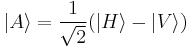
| Linear polarized at −45° from the x-axis Typically called 'Anti-Diagonal' L-45 |
 |
 |
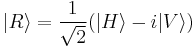
| Right Hand Circular Polarized Typically called RCP or RHCP |
 |
 |
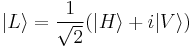
| Left Hand Circular Polarized Typically called LCP or LHCP |
 |
 |
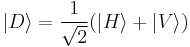
When applied to the Poincare sphere (also known as the Bloch sphere), the basis kets ( and
and  ) must be assigned to opposing (antipodal) pairs of the kets listed above. For example, one might assign = and = . These assignments are arbitrary. Opposing pairs are
- and
 and
and 
 and
and 
The  ket is a general vector that points to any place on the surface. Any point not in the table above and not on the circle that passes through
  is collectively known as elliptical polarization.
Jones matrices
The Jones matrices are the operators that act on the Jones Vectors as listed above. These matrices are implemented by various optical elements such as lenses, beam splitters, mirrors, etc. The following table gives examples of Jones Matrices for Polarizers:
| Optical element | Corresponding Jones matrix |
| Linear polarizer with axis of transmission horizontal |
|
| Linear polarizer with axis of transmission vertical |
|
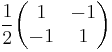
| Linear polarizer with axis of transmission at 45° with the horizontal |
|
| Linear polarizer with axis of transmission at -45° with the horizontal |
|
| Right circular polarizer |
|
| Left circular polarizer |
|
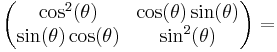
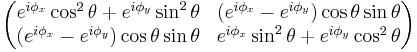
Linear polarizer with axis of transmission at angle  with the horizontal. (Shown construction from rotating up from the horizontal into the polarizing element, the polarizing element, and then rotating back down into the horizontal.) with the horizontal. (Shown construction from rotating up from the horizontal into the polarizing element, the polarizing element, and then rotating back down into the horizontal.) |
|


Phase retarders
Phase retarders introduce a phase shift between the vertical and horizontal component of the field and thus change the polarization of the beam. Phase retarders are usually made out of birefringent uniaxial crystals such as calcite, MgF2 or quartz. Uniaxial crystals have one crystal axis that is different from the other two crystal axes (i.e., ni ≠ nj = nk). This unique axis is called the extraordinary axis and is also referred to as the optic axis. An optic axis can be the fast or the slow axis for the crystal depending on the crystal at hand. Light travels with a higher phase velocity through an axis that has the smallest refractive index and this axis is called the fast axis. Similarly, an axis which has the highest refractive index is called a slow axis since the phase velocity of light is the lowest along this axis. Negative uniaxial crystals (e.g., calcite CaCO3, ruby Al2O3) have ne < no so for these crystals, the extraordinary axis (optic axis) is the fast axis whereas for positive uniaxial crystals (e.g., quartz SiO2, magnesium fluoride MgF2, rutile TiO2), ne > n o and thus the extraordinary axis (optic axis) is the slow axis.
Any phase retarder with fast axis vertical or horizontal has zero off-diagonal terms and thus can be conveniently expressed as
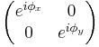
where, and are the phases of the electric fields in  and
and  directions respectively. In the phase convention , the relative phase between the two waves when represented as
  suggests that a positive
  (i.e., > ) means that
  doesn't attain the same value as
  until a later time i.e., leads . Similarly, if
  i.e., > , leads . For e.g., if the fast axis of a quarter wave plate is horizontal, this suggests that the phase velocity along the horizontal direction is faster than that in the vertical direction i.e., leads . Thus,
  which for a quarter wave plate suggests that
  .
.
In the opposite convention , the relative phase when defined as  suggests that a positive means that doesn't attain the same value as until a later time i.e., leads .
| Phase retarders | Corresponding Jones matrix |
|---|---|
| Quarter-wave plate with fast axis vertical |
|
| Quarter-wave plate with fast axis horizontal |
|
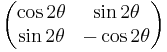
| Half-wave plate with fast axis at angle w.r.t the horizontal axis[1] |
|
| Any birefringent material (phase retarder)[2] |
|


The special expressions for the phase retarders can be obtained by using the general expression for a birefringent material. In the above expression:
- Phase retardation induced between and by a birefringent material is given by

- is the orientation of the fast axis with respect to the x-axis.
 is the circularity (For linear retarders, = 0 and for circular retarders, = ±
  /2. For elliptical retarders, it takes on values between - /2 and /2).
Rotated elements
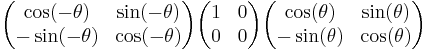
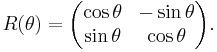
If an optical element is rotated about the optical axis by angle θ, the Jones matrix for the rotated element, M(θ), is constructed from the matrix for the unrotated element, M, by the transformation
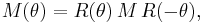
- where
See also
Notes
- ^ A. Gerald and J.M. Burch, Introduction to Matrix Methods in Optics,1st ed., John Wiley & Sons(1975). ISBN 0-471-29685-6
- ^ Obtainment of the polarizing and retardation parameters of a non-depolarizing optical system from the polar decomposition of its Mueller matrix, Optik, Jose Jorge Gill and Eusebio Bernabeu,76, 67-71 (1987).
References
- E. Collett, Field Guide to Polarization, SPIE Field Guides vol. FG05, SPIE (2005). ISBN 0-8194-5868-6.
- D. Goldstein and E. Collett, Polarized Light, 2nd ed., CRC Press (2003). ISBN 0-8247-4053-X.
- E. Hecht, Optics, 2nd ed., Addison-Wesley (1987). ISBN 0-201-11609-X.
- Frank L. Pedrotti, S.J. Leno S. Pedrotti, Introduction to Optics, 2nd ed., Prentice Hall (1993). ISBN 0-13-501545-6
- A. Gerald and J.M. Burch, Introduction to Matrix Methods in Optics,1st ed., John Wiley & Sons(1975). ISBN 0-471-29685-6
- Jones, R. Clark (1941). "A new calculus for the treatment of optical systems, I. Description and Discussion of the Calculus". Journal of the Optical Society of America 31 (7): 488–493. doi:10.1364/JOSA.31.000488.
- Hurwitz, Henry; Jones, R. Clark (1941). "A new calculus for the treatment of optical systems, II. Proof of three general equivalence theorems". Journal of the Optical Society of America 31 (7): 493–499. doi:10.1364/JOSA.31.000493.
- Jones, R. Clark (1941). "A new calculus for the treatment of optical systems, III The Sohncke Theory of optical activity". Journal of the Optical Society of America 31 (7): 500–503. doi:10.1364/JOSA.31.000500.
- Jones, R. Clark (1942). "A new calculus for the treatment of optical systems, IV". Journal of the Optical Society of America 32 (8): 486–493. doi:10.1364/JOSA.32.000486.
- Fymat, A. L. (1971). "Jones's Matrix Representation of Optical Instruments. I: Beam Splitters". Applied Optics 10 (11): 2499–2505. Bibcode 1971ApOpt..10.2499F. doi:10.1364/AO.10.002499. PMID 20111363.
- Fymat, A. L. (1971). "Jones's Matrix Representation of Optical Instruments. 2: Fourier Interferometers (Spectrometers and Spectropolarimeters)". Applied Optics 10 (12): 2711–2716. Bibcode 1971ApOpt..10.2711F. doi:10.1364/AO.10.002711.
- Fymat, A. L. (1972). "Polarization Effects in Fourier Spectroscopy. I: Coherency Matrix Representation". Applied Optics 11 (1): 160–173. Bibcode 1972ApOpt..11..160F. doi:10.1364/AO.11.000160. PMID 20111472.
- Gill, Jose Jorge; Bernabeu, Eusebio (1987). "Obtainment of the polarizing and retardation parameters of a non-depolarizing optical system from the polar decomposition of its Mueller matrix,". Optik 76: 67–71.
- Brosseau, Christian; Givens, Clark R.; Kostinksi, Alexander B. (1993). "Generalized trace condition on the Mueller-Jones polarization matrix". Journal of the Optical Society of America A 10 (10): 2248–2251. Bibcode 1993JOSAA..10.2248B. doi:10.1364/JOSAA.10.002248.
- McGuire, James P.; Chipman, Russel A. (1994). "Polarization aberrations. 1. Rotationally symmetric optical systems". Applied Optics 33 (22): 5080–5100. doi:10.1364/AO.33.005080. PMID 20935891.
- Pistoni, Natale C. (1995). "Simplified approach to the Jones calculus in retracing optical circuits". Applied Optics 34 (34): 7870–7876. Bibcode 1995ApOpt..34.7870P. doi:10.1364/AO.34.007870. PMID 21068881.
- Moreno, Ignacio; Yzuel, Maria J.; Campos, Juan; Vargas, Asticio (2004). "Jones matrix treatment for polarization Fourier optics". Journal of Modern Optics 51 (14): 2031–2038. doi:10.1080/09500340408232511.
- Moreno, Ivan (2004). "Jones matrix for image-rotation prisms". Applied Optics 43 (17): 3373–3381. Bibcode 2004ApOpt..43.3373M. doi:10.1364/AO.43.003373. PMID 15219016.